Progress Bar

Skip to main content

Jaycar
...

Symbol Keyboard

Symbol Keyboard

Difficulty
Test & Tools

Summary

Many of the articles that we write include scientific, mathematical or typographic symbols that aren’t easily entered with a keyboard. In Windows, for example, some symbols can be entered from the so-called Emoji Panel; previously, tools like Character Map allowed symbols to be copied to the clipboard for pasting into a document. However, those methods are slow and awkward.

Windows also supports ‘Alt codes’, which allow a code (corresponding to a specific symbol or character) to be entered on the numeric keypad. Many of the available characters come from what is known as Code Page 1252.

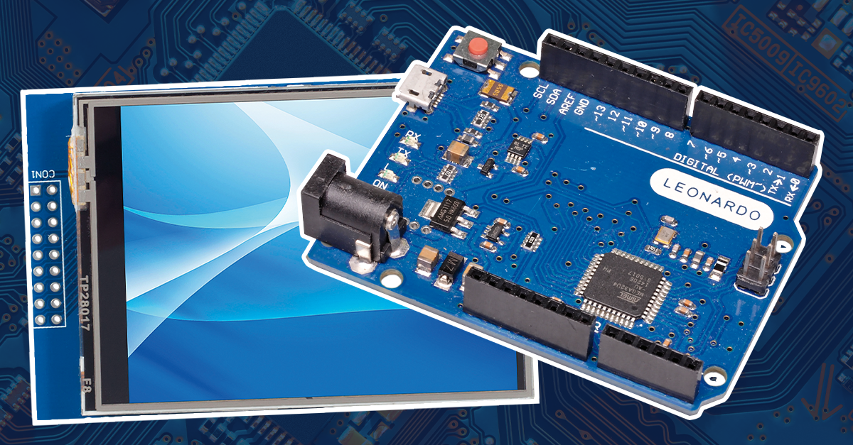
Since a Leonardo board can emulate a USB keyboard, it can generate these key sequences as needed. While a series of pushbuttons could be used for input, we have decided to use an LCD touch panel, as it allows us to customise the available symbols.

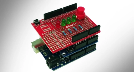
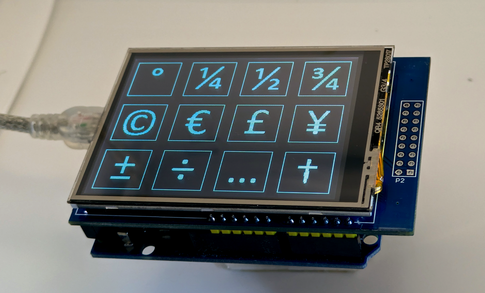
By using a display shield, assembly is simple: just plug the shield into the Leonardo board. Of course, it needs to be programmed; we have used the Arduino IDE for this, so it is easy to modify or customise.

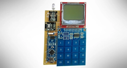
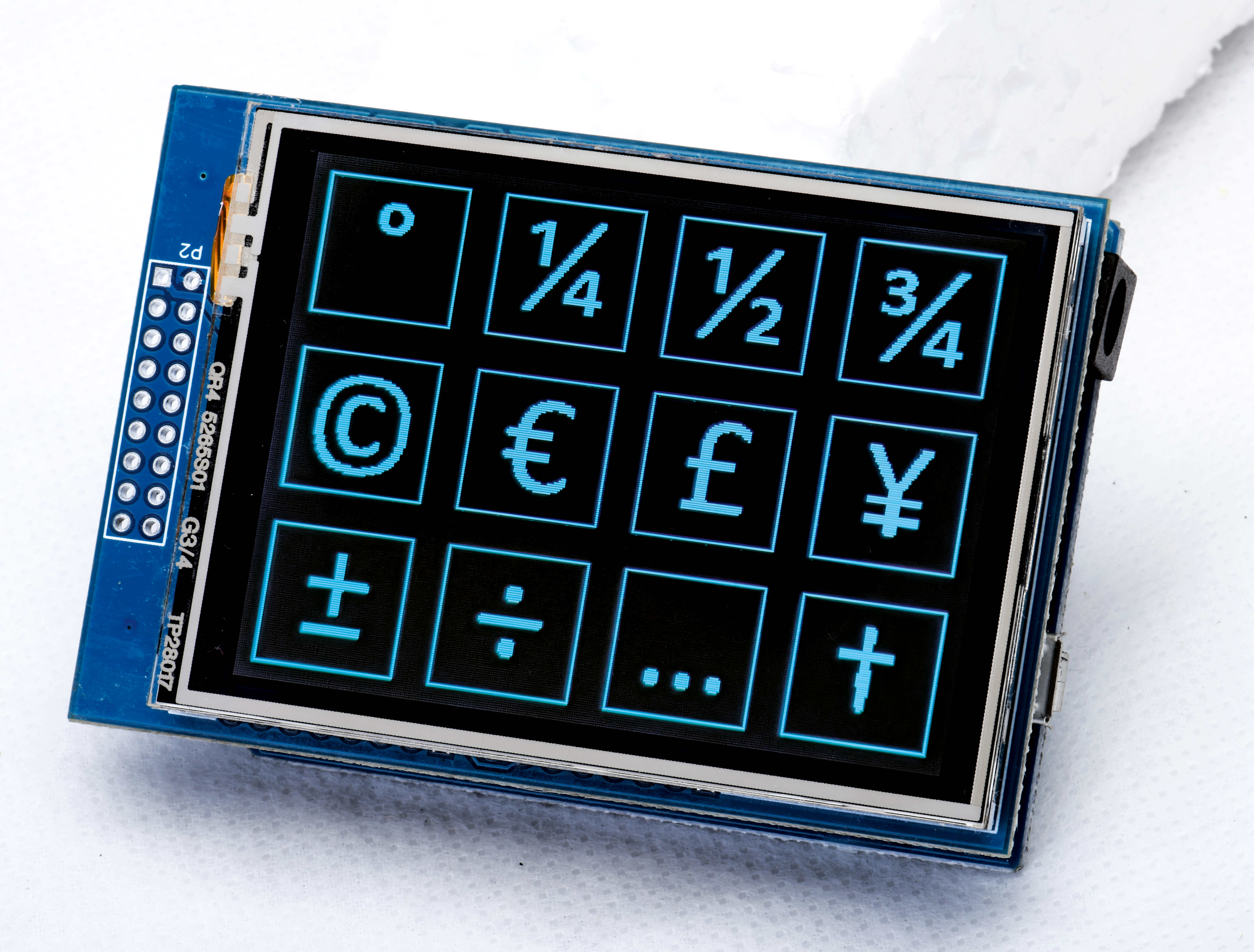
The photo above shows a complete Symbol Keyboard populated with our choice of symbols. We often use these symbols when writing our articles, but there are many other useful ones in the Windows Code Page 1252 set. Many are accented letters used in languages other than English.

Note that the Alt codes scheme only works on Windows computers, so this keyboard will not work on other operating systems. Alt codes should also work in Linux, but for macOS, you would have to modify the software to use either Option codes or text replacements.

Materials Required

1Duinotech Leonardo r3 Main BoardXC4430
1Duinotech Arduino Compatible 2.5 Inch Colour LCD Touch Screen DisplayXC4630
10.5m USB A male to Micro-B CableWC7723

Plug the display shield into the Leonardo and use the USB cable to connect it to a computer. That completes the physical assembly! Next, download the sketch (siliconchip.au/Shop/6/378), extract the ZIP file, open the sketch with the Arduino IDE and upload the sketch. You shouldn’t need any external libraries.

While the sketch is compiling, open a text editor window (eg, Notepad) to test the Symbol Keyboard. This will also help to catch any stray keystrokes if there is a problem.

You should see the LCD screen initialise with the graphics seen in our photos. Pressing any of the symbols on the display panel should cause the corresponding symbol to be typed into the text editor. In that case, all is well.

If your display is not correct, try pressing the touch panel to see if that triggers keystrokes. That should still work even if the display is wrong. If the touch panel isn’t responding, try reprogramming the Leonardo.

leoandshield.png

The software is relatively straightforward. It displays a series of symbol buttons on the LCD and waits for a touch to be registered on one of them, after which it sends the appropriate key sequence to the attached computer.

The Arduino AVR board profile (which supports the Leonardo) includes the keyboard library. We have written a function that wraps the sequence needed to send the Alt code.

The XC4630d.c file is customised for the specific display shield we’re using; you might need to set the shield version near the top of this file. We’re using the XC4630_v4 #define, which works well with a recently obtained shield sample.

The bitmaps.c file contains the data for displaying the symbol images on the screen. We created them as 64×64 pixel files in Microsoft Paint by entering the necessary Alt codes to create matching text characters at a 48-point size.

We then used the online converter at siliconchip.au/link/abu6 to generate the data used in the program. You can use similar steps to create your own custom symbol images.

You also need to set correct Alt codes to ‘type’ them. We found them on the Wikipedia page at https://w.wiki/9SGq

We knew they would type the corresponding characters later since we used the Alt codes to generate the corresponding bitmaps.

To customise the symbols, you must change the Alt code in the codes[] array. The appropriate code can be found in the Windows 1252 Code Page (link above). You will also need to add a matching monochrome bitmap to the bitmaps.c file and add a reference to that in the bitmaps[] array.

Apart from creating custom bitmaps to display different symbols, the orientation of the buttons on the display can be changed too. The XC4630_rotate() command in setup() determines the orientation.

Values 2 and 4 are landscape mode, while values 1 and 3 give portrait orientation. ROWS and COLUMNS should be changed to 4 and 3 to make the portrait orientation work correctly.

The BUTTON_WIDTH and BUTTON_HEIGHT #defines determine the spacing between the buttons. Using a spacing of 80 pixels with bitmaps measuring 64 pixels means that there is a comfortable amount of room between them.

If you are confident with the Arduino IDE, you can change these values to fit more buttons and thus symbols on the display. You could create smaller bitmaps too.

The colours can also be changed by modifying the FGC and BGC #defines. The available colour names are listed in the XC4630d.c file. Other 16-bit (RGB565) colour values can be used here instead.

Note that you must re-upload the sketch for any changes to take effect.

It’s a simple build, but the Symbol Keyboard has already become a handy tool for us while we write our articles. We can’t believe we didn’t think of it earlier!

symbol-keyboard-final.png

This article appeared in the May 2024 issue of Silicon Chip Magazine. Check out their website for other project ideas: https://www.siliconchip.com.au/

Similar projects you may be interested in

Test & Tools
ATtiny Programmer Shield
Difficulty

USB Serial Converter
Test & Tools
Arduino Tool: USB-Serial Converter
Difficulty

Test & Tools
Revive your Arduino - ISP Programming
Difficulty

digital-compass-thumbnail.jpg
Test & Tools
Digital Compass
Difficulty