Arduino RFID Keypad
Difficulty
Security & Surveillance
Summary
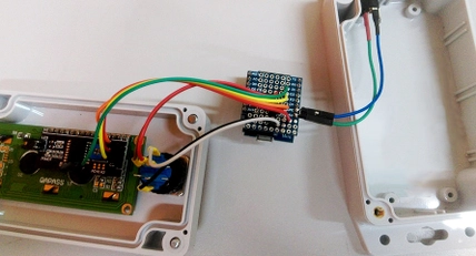
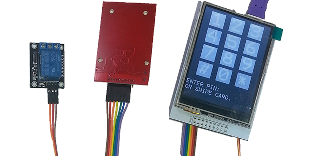
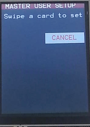
Here's a security project designed with versatility in mind- it's inspired by our LA5353 RFID Keypad, but because it uses the XC4630 LCD Touchscreen, the setup of cards and users is a bit easier. As with most Arduino security stuff, it's pretty easy to bypass if you have physical access to the main board, so we wouldn't recommend using it for protecting valuables. Still, if you want to be able to activate a relay with either a card (most smartcards like public transport cards and bank cards will work with it) or a PIN code, this project fits the bill. There is some soldering required for this project.
Materials Required
| 1 | Duinotech UNO r3 Main Board | XC4410 |
| 1 | 150mm Plug to Socket Jumper Leads - 40 Pieces | WC6028 |
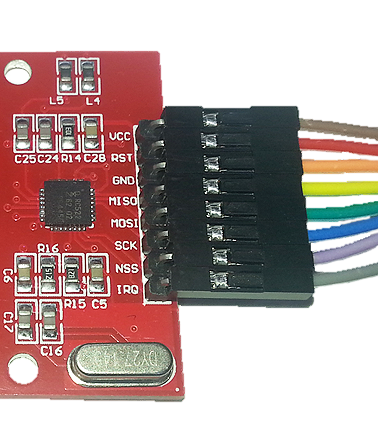
| 1 | Duinotech Arduino Compatible RFID Read and Write Module | XC4506 |
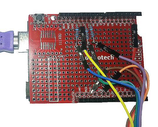
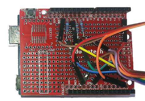
| 1 | Duinotech Arduino Compatible Prototyping Shield | XC4482 |
| 1 | Arduino Compatible 5V Relay | XC4419 |
| 1 | Duinotech Arduino Compatible 2.5 Inch Colour LCD Touch Screen Display | XC4630 |
| 1 | 10k Ohm 0.5 Watt Metal Film Resistors - Pack of 8 | RR0596 |
Resources
Similar projects you may be interested in