Intruder Alert
Difficulty
Security & Surveillance
Summary
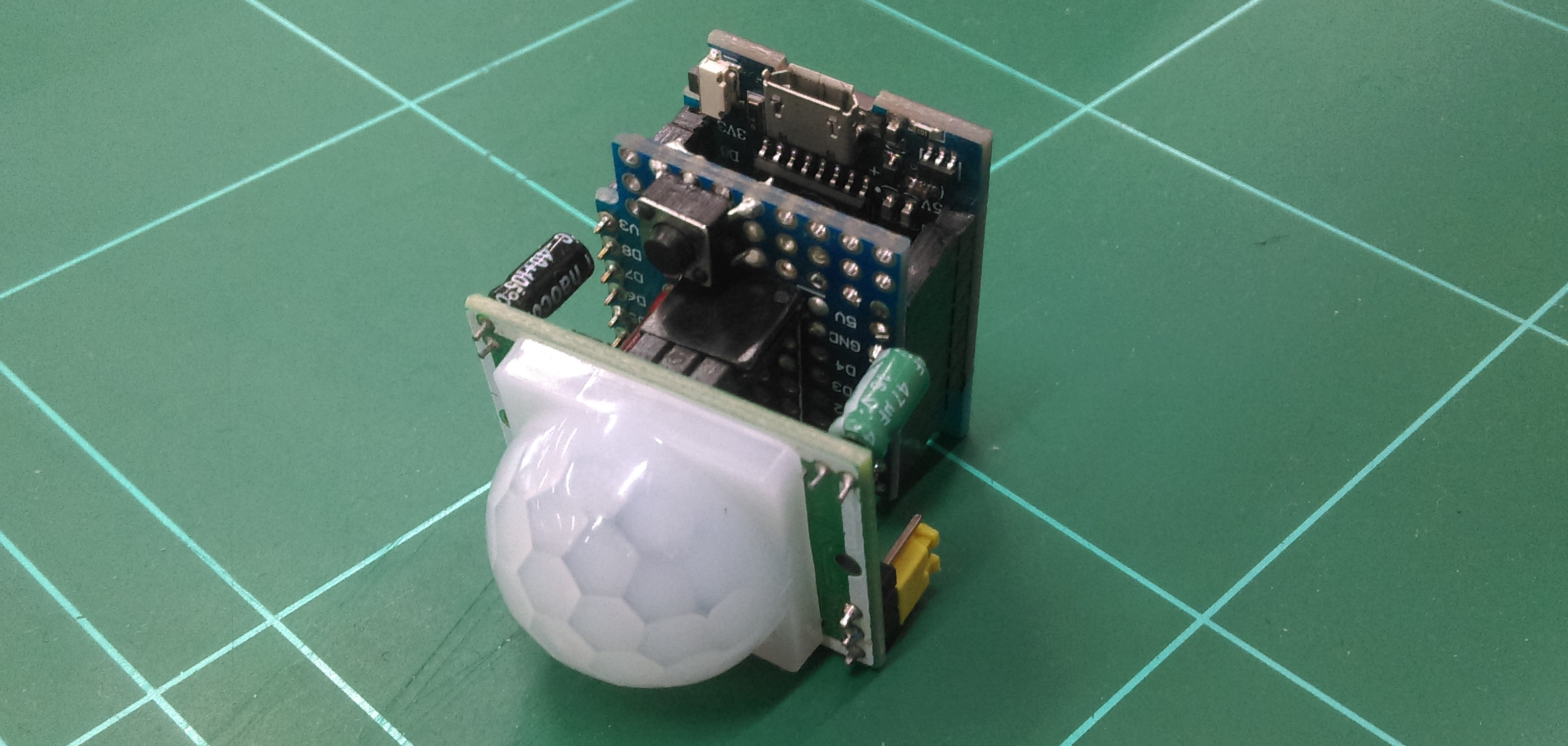
This is an updated version of our Intruder Alert project; designed to be both easier to manage and more secure.
The ideas don't just stop at a PIR sensor either; The code is very simple to understand and through the IFTTT service you can cause anything to trigger; such as using a button or light sensor.
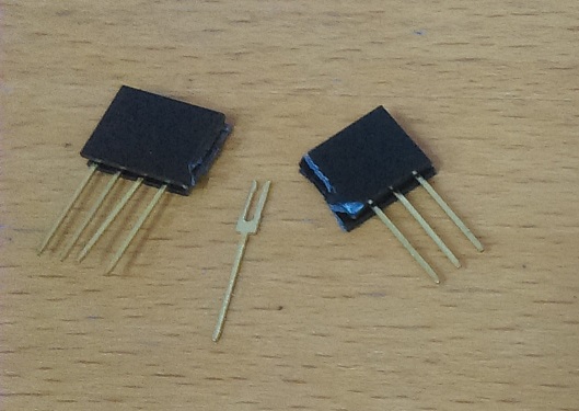
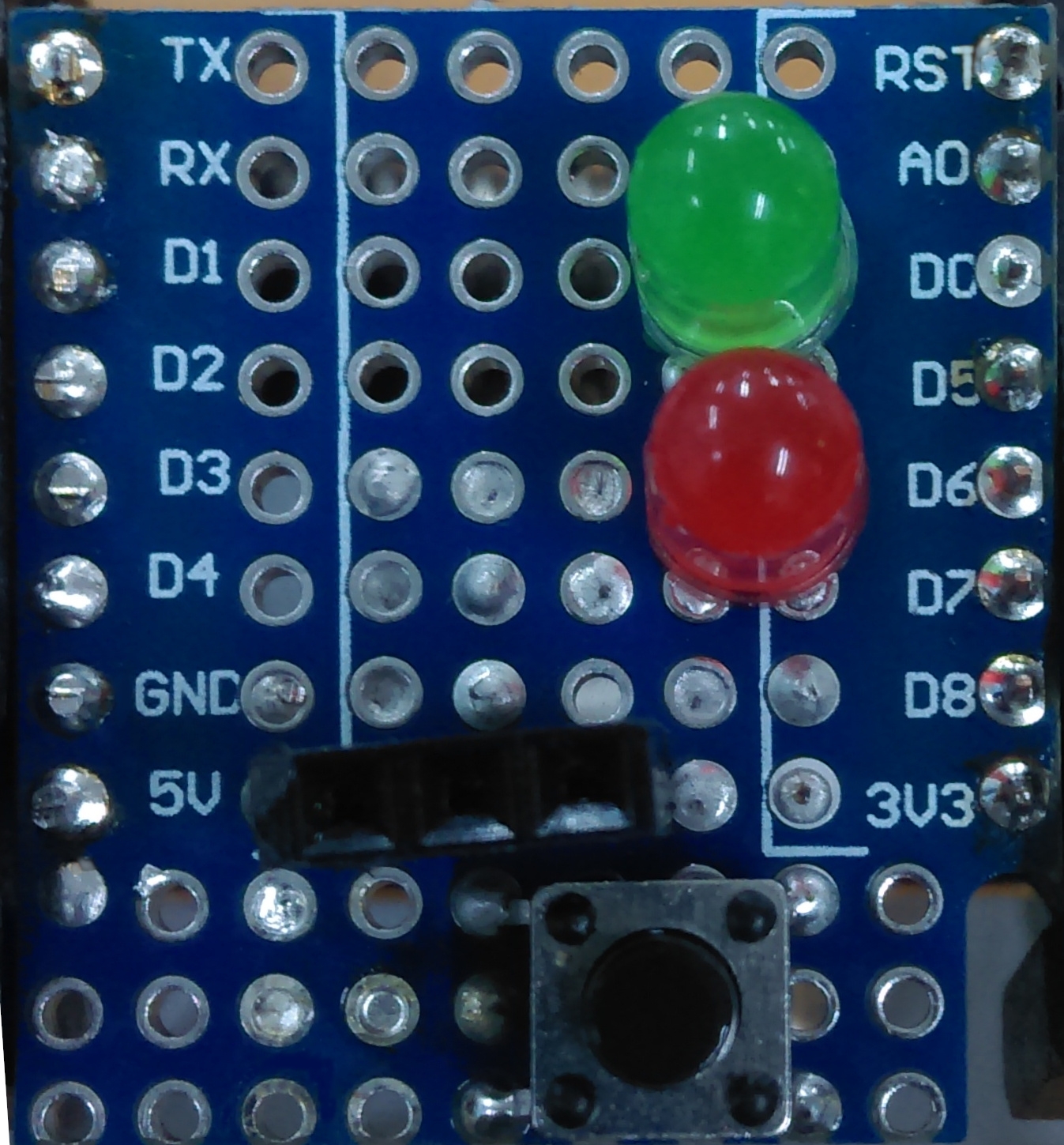
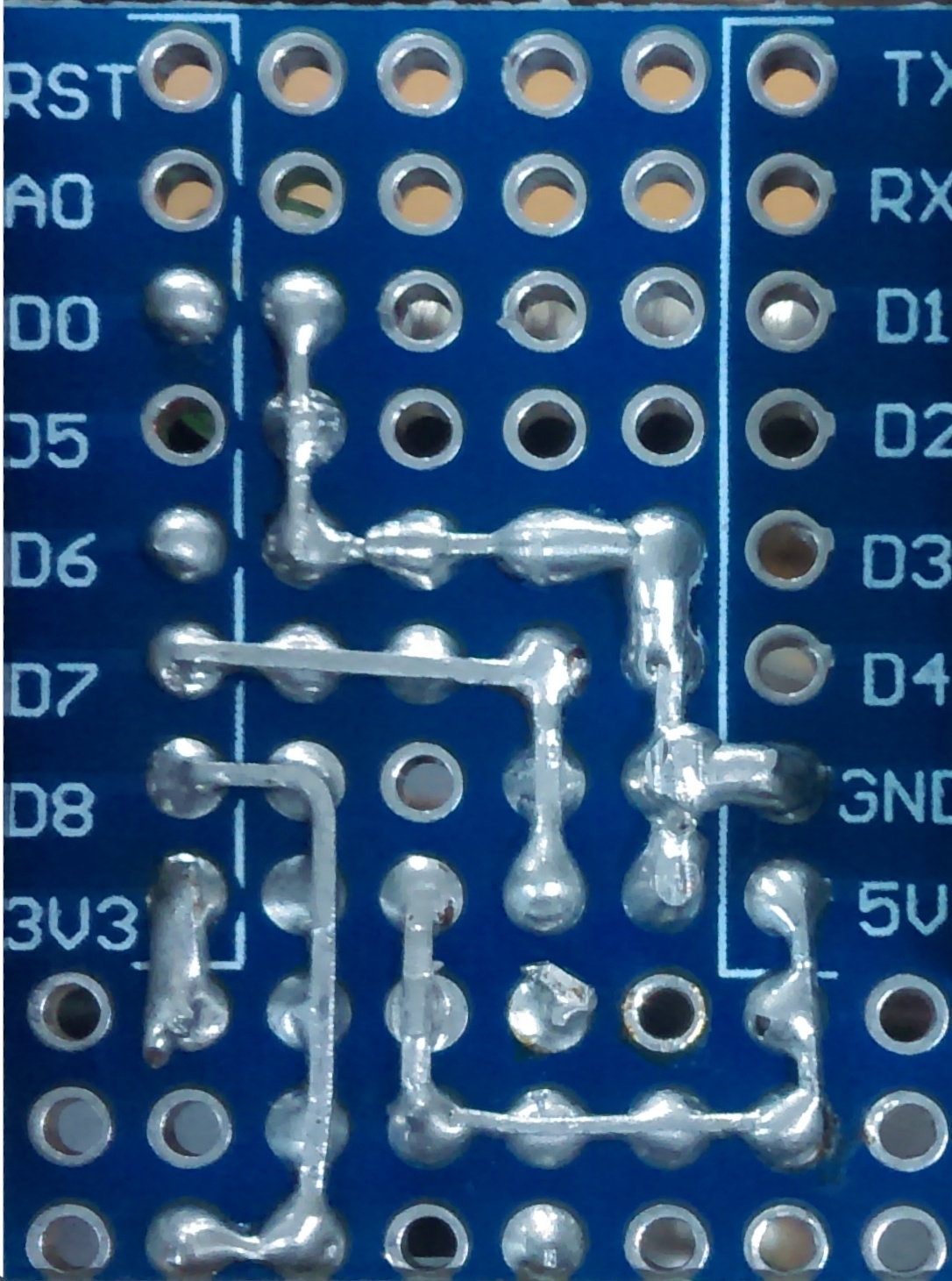
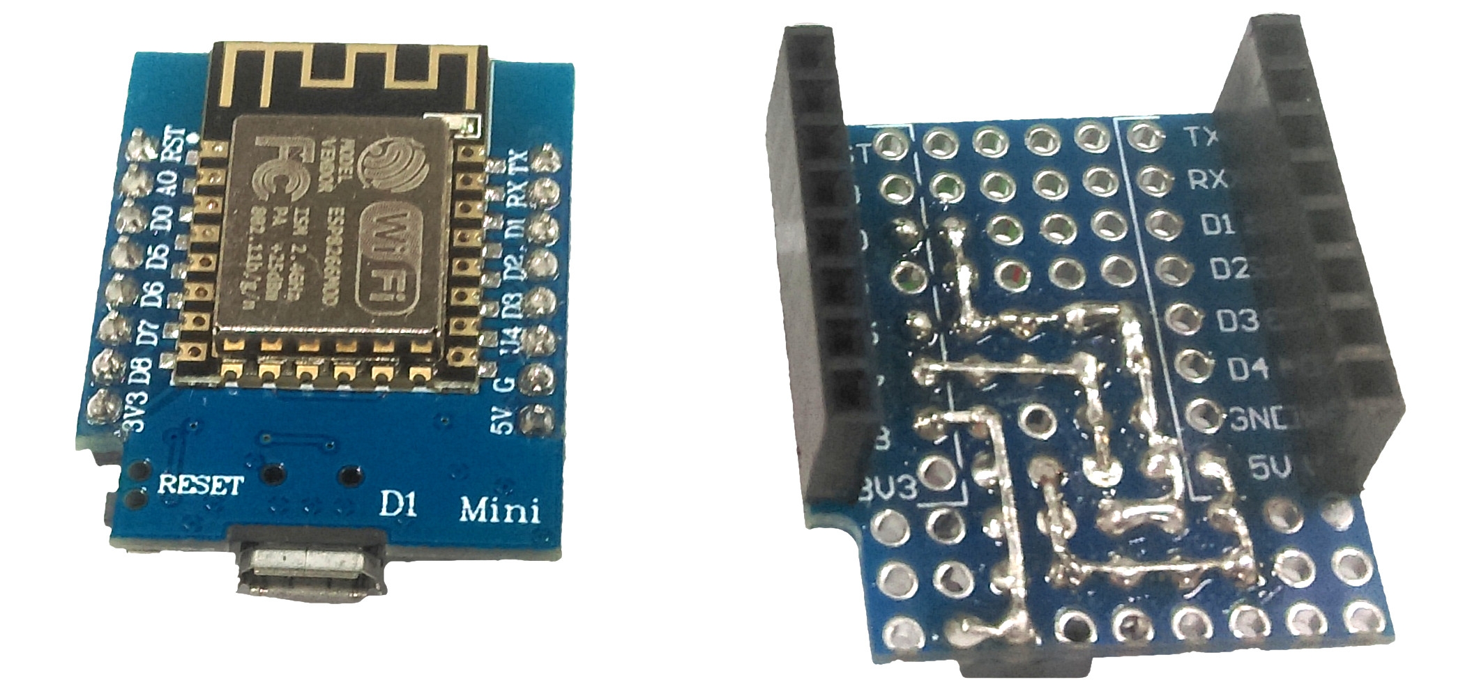
Note: The off-cuts of the LEDs are used to bridge connections on the PCB board. If you want you can include WH3032 to have plenty of spare solid core wire around.
Materials Required
| 1 | Wi-Fi Mini ESP8266 Main Board | XC3802 |
| 1 | Arduino Compatible Wi-Fi Mini Prototyping Shield | XC3850 |
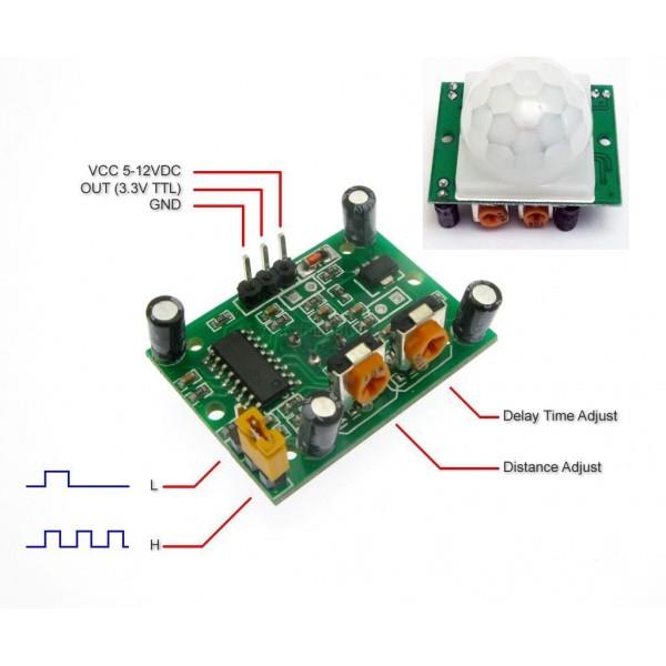
| 1 | Duinotech Arduino Compatible PIR Motion Detector Module | XC4444 |
| 1 | Red 5x2mm LED 5mcd Rectangular Diffused | ZD0230 |
| 1 | Green 5x2mm LED 15mcd Rectangular Diffused | ZD0232 |
| 1 | 1.4mm SPST Micro Tactile Switch | SP0601 |
Similar projects you may be interested in



.jpg?branch=prod)


