Progress Bar

Skip to main content

Jaycar
...

Silent Alarm Clock

Silent Alarm Clock

Difficulty
Sight & Sound

Summary

Do you need an alarm clock that doesn't wake anyone up next door? Do you often look at the time and immediately fall asleep again? Well look no further. This Silent Alarm Clock uses RGB LED shield to provide a great colourful display in your bedroom and simulate daylight to gently wake your body up.

If you want to know what time it is, just give two loud claps and the Silent Alarm Clock will read out the current time to give your brain a quick morning jog.

timelapse.gif

Input

Output

Time

RGB Colour

Claps

Time

Materials Required

1Duinotech UNO r3 Main BoardXC4410
1Duinotech Arduino Compatible 8 x 5 RGB LED Matrix ShieldXC3730
1Arduino Compatible Microphone Sound Sensor ModuleXC4438

system.png

This is a simple 'clock' device that will change the colour of the shield depending on the time – appearing more red at night to allow you to sleep and in the morning, changing to whitish-blue colours to gently wake you up.

It will also have a clap-detector built into it; so when you clap twice (think: "the clapper"), the device outputs what time it is on the RGB Matrix in a nice yellow colour.

Naturally, when the system detects the claps, it will interrupt the "rainbow" effects to display the time in a straightforward manner.

Firstly, you will want to remove and clean up the pins and the blue pot on the module so that it can fit under the shield. The pins can be straightened out with a pair of pliers, then use the technique mentioned in the Removing Headers tutorial.


cleaning.jpg


The potentiometer is a little different; you should be able to heat up two pads at once, pulling out that side of the potentiometer and gently wiggling it out of the PCB. Use plenty of solder wick (NS3026) or you can try your hand with a solder sucker (TH1862) to remove the solder. Tip: you might find it easier to apply fresh solder to the pad.

removed.jpg

Once the audio module does not have pins or the potentiometer on it, use some spare headers (or small wires) to mount the module to the data logger shield. We've outlined where you want to place the headers, but you can put them anywhere you want (if you want to have a buzzer or other improvements down the line, be sure to leave space; we've placed this in the centre just out of simplicity).

layout.jpg


You'll find that this layout allows the audio module to be mounted on top very nicely. You can then solder on the audio module and put the potentiometer in place right next to it.

pot.jpg

This effectively moves the potentiometer across and lower so it can fit under the shield; electrically it all works out the same once you connect it to the header pins:

wire.jpg

Use some solid core wires to connect the + and GND connections, as well as D0 to Pin 2 on the arduino. D0 is going to be our clap detection, which we wire to Pin 2 so that it can trigger an interrupt.

wiring.jpg

First use the calibrate.ino sketch to set up the RTC and test the clapper. Use a small screwdriver on the blue potentiometer so that when you make a loud noise (like a clap), the LED will be on for a short while. Follow the instructions in the Serial Monitor for more information.

When you upload calibrate.ino, the sketch will adjust the rtc to be the same as the computer time the moment you press upload. Each reset you do will adjust it to the same time and date.

When you’re happy with the calibration results, it’s generally a good idea to upload the sketch again so that it correctly adjusts the time. Then you can open up and upload the clock.ino so that it doesn't change the time again. When we upload the clock.ino sketch, it removes the rtc.adjust so that there's no more adjusting and the rtc happily ticks away at the correct time.

Simply observe, and clap twice; you should find that it outputs the time onto the LED matrix.

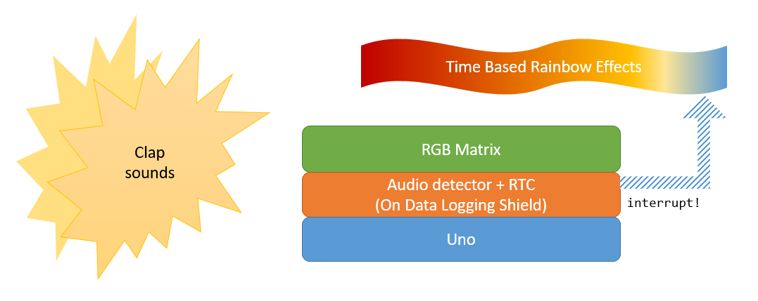
The source code is simple enough; with the basic setup() and loop() functions below:

void setup(){    // put your setup code here, to run once:    Serial.begin(9600);    shield.begin();    shield.setBrightness(100);    pinMode(pin_sensor, INPUT);    pinMode(pin_buzzer, OUTPUT);    //we define the "detectClaps" function in the sketch    attachInterrupt(digitalPinToInterrupt(pin_sensor),detectClaps, RISING);    setupRTC();}void loop(){    DateTime realTimeNow = rtc.now();    // ...     //always display colour on the matrix, corresponding to time    setColourFromTime(realTimeNow);    if (hasClapped){        //we have detected two claps, print in "hh:mm" format        shield.print(realTimeNow.toString("hh:mm"));    }}

The setColourFromTime() function is simply a collection of if-statements to block off portions of the day:

if(hours < morningTime){    // between 0 -> 6am    // change from red to whitish blue to wake up}else if (hours > morningTime && hours < afternoonTime){    // 6am -> 4pm    // show mainly blue, some white, etc}// etc

Then while we're doing this, the detect claps function is a simple interrupt that will check for two claps in a reasonable time frame. We "debounce" the claps so that any ringing effects aren't misunderstood as a second clap.

//fired any time the audio module detects noisevoid detectClaps(){    unsigned long timeNow = millis();    if (firstClapTime == 0)    {        firstClapTime = timeNow;        return;    }    unsigned long duration = timeNow - firstClapTime;    if (duration > clap_debounce_ms && duration < clap_delay_ms)    {        //two claps genuine; set clapped flag        firstClapTime = 0;        hasClapped = true;    }    else if (duration > clap_delay_ms)    {        //timeout.. took too long        firstClapTime = 0;    }}

We have also included a #define TIMELAPSE comment that you can comment out to test what it will look like over the course of a whole day. If you uncomment this define, it will rapidly move through the time in the day and output the time in Serial.

Similar projects you may be interested in

Atari Punk Synth
Sight & Sound
Atari Punk Synth
Difficulty

Sight & Sound
Arduino Power Saving and Battery Night Light
Difficulty

WiFi LED Lightstrip
Sight & Sound
WiFi Controlled Strip Lighting
Difficulty

Arduino Clap Light
Sight & Sound
Arduino Clap Light
Difficulty