Progress Bar

Skip to main content

Jaycar
...

Morse Trainer

Morse Trainer

Difficulty
Signt & Sound
Summary

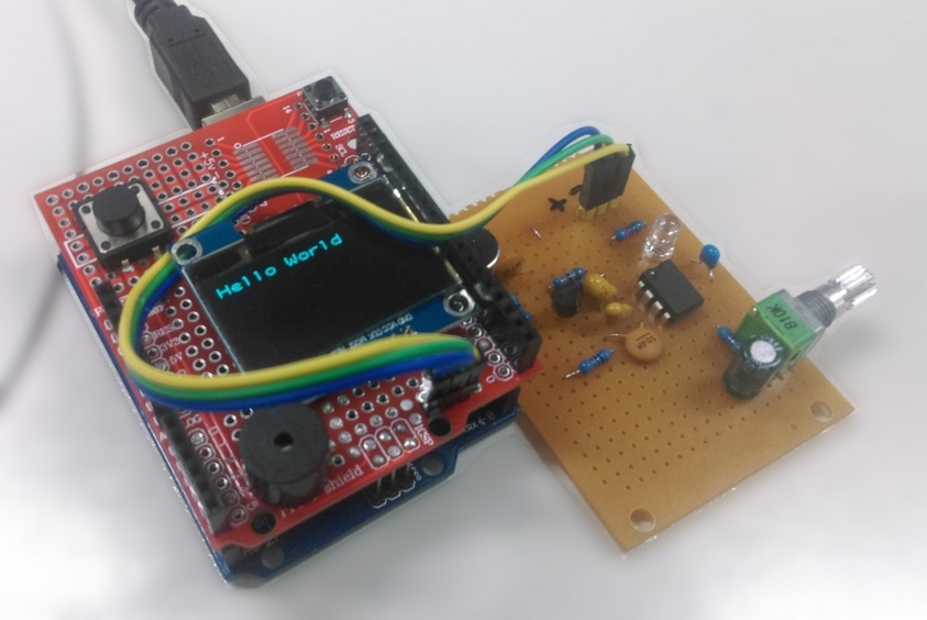
Listen to secret coded messages on the short-wave radio with this real time Morse code to text translator! This project uses a 567 Tone Decoder IC to filter out unwanted audio and feeds a clear signal to the Arduino for real time decoding on the (XC3728) OLED screen. This project comes in two parts, with the filter on a separate PCB and the Arduino shield containing a buzzer and a push button for Morse sending practice. Of course, you could always attach your own key!

Materials Required

1Duinotech UNO r3 Main BoardXC4410
1Duinotech Arduino Compatible 1.3 Inch Monochrome OLED DisplayXC3728
1LM567 Low Power Tone Decoder Linear ICZL3567
1Ultra Mini Experimenters BoardHP9556
1BC548 NPN TransistorZT2154
1Standard Microphone Insert with PinsAM4011
1Green 5mm LED 7500mcd Round ClearZD0172
1Duinotech Arduino Compatible Prototyping ShieldXC4482
1Mini PCB Mount Buzzer 9-14VDCAB3459
1SPST PCB Mount Tactile Switch RoundSP0609
128 Pin Header Terminal StripHM3211
1150mm Socket to Socket Jumper Leads - 40 PieceWC6026
110k Ohm Linear (B) Single Gang 9mm PotentiometerRP8510
11M Ohm 0.5 Watt Metal Film Resistors - Pack of 8RR0644
1330k Ohm 0.5 Watt Metal Film Resistors - Pack of 8RR0632
14.7k Ohm 0.5 Watt Metal Film Resistors - Pack of 8RR0588
110k Ohm 0.5 Watt Metal Film Resistors - Pack of 8RR0596
1220nF 50VDC Monolithic CapacitorRC5494
1100nF 50VDC Ceramic Capacitors - Pack of 2RC5360
11uF 25VDC Tantalum CapacitorRZ6627
12.2uF 35VDC Tantalum CapacitorRZ6632

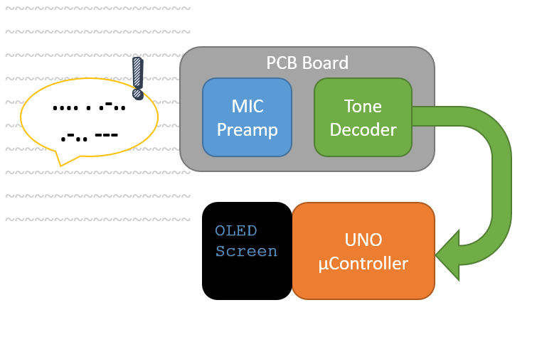
The basic idea to this project is pretty simple, we will create a PCB board that can pick up a filtered tone and send that to the arduino to be processed and translated from morse code into text, and put that on to the OLED screen. The will also just have a buzzer and a button on it so we can reply back in morse code, and through this we can also attach the serial monitor, so that we can do audio communications through the serial terminal.

The meat of this project, funnily enough, is on that PCB board. We are using the 567 Tone Decoder IC so that we can selectively filter out background noise. The tone decoder will only output a value when it hears the correct frequency though it's input pin, which is fed through by a Microphone and pre-amp.

Most morse transmissions (through audio) is heard at about a 400Hz - 700Hz tone, you can easily check this out by listening to any morse recordings on youtube; One good one we used for testing is: https://youtu.be/-ej5AmTYFC0?t=30

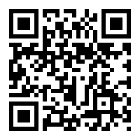
You can scan this to open the youtube video on your phone, which you can hold to the microphone while developing.

Microphone pre-amp

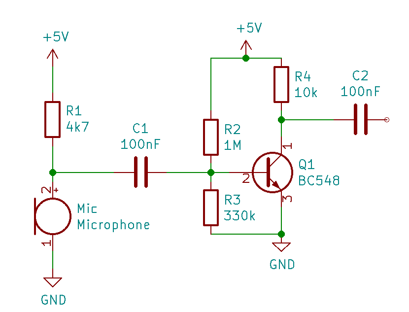
The first part we'll talk about is the microphone and pre-amp circuit, below.

We won't be talking too much about what's going on here; you should be be able to build it and get decent results. The main dot points are:

  • The microphone (is polarity sensitive, the case is grounded) is pulled up to 5V with the 4.7k resistor.

  • the capacitors in the circuit do nothing other than to separate the DC signals from both sides of the circuit. Capacitors block DC and allow through AC, which is what audio signals are.

  • The transistor circuit provides the boost. it's the amp in "pre-amp" and will take the power of the circuit to be a lot stronger and able to be picked up by the tone decoder IC. For information on biasing the transistor, check out the Further Reading section; but you can just copy what we have here without issues.

Tone Decoder IC

After the transistor and the capacitor, the signal is fed into our 567 Tone Decoder IC, which will output (active low) the signal that it picks up, tuned to a specific frequency.

The circuit what we are going for is below, you can read the datasheet for the tone decoder IC to find the calculations on selecting the right frequency.

Note the pin numbering on the above diagram, it's a little out of order to make it easier for the schematic view, however on the board, C3 C4 and C5 are next to each other ( You'll see the board soon.) C2 is the same C2 from the preamp circuit.

As mentioned, the active output of the 567 is LOW, which will ground the LED which turns the LED on. this also means that the signal is inverted when it goes to the UNO, which is something to keep in mind.

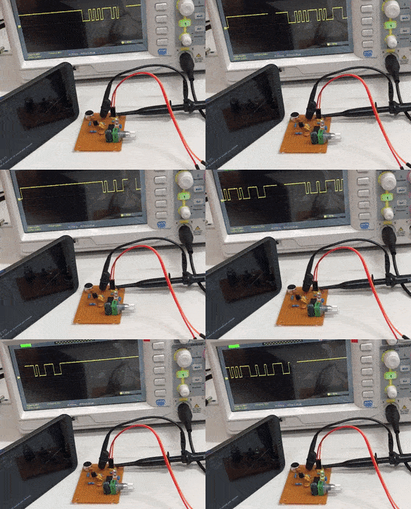
Once the two parts are made, you can easily test them with an oscilloscope such as our QC1936 and see the nice clean signal as it comes through

test.gif

Building the boards

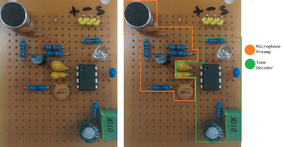
Next up we'll talk about building the boards themselves. Firstly the tone decoder board.


Note, in our pcb we used an electrolytic cap, located near the potentiometer; this won't be needed in your project

We've highlighted the separation of the two parts, the microphone pre-amp and the tone decoder IC sections. This makes it a little easier to visualise what's going on and how the two parts fit together. It might be easier to first make the pre-amp circuit first and fit in the tone decoder afterwards. It's also worth while to play around with the circuit on a breadboard so you know how the tone decoder works.

You can see on pin 3 of the tone decoder IC, the cap (with the label of 104M = 100nF) is what connects the collector of the transistor to the IC. This is what we have in the schematics above as well.

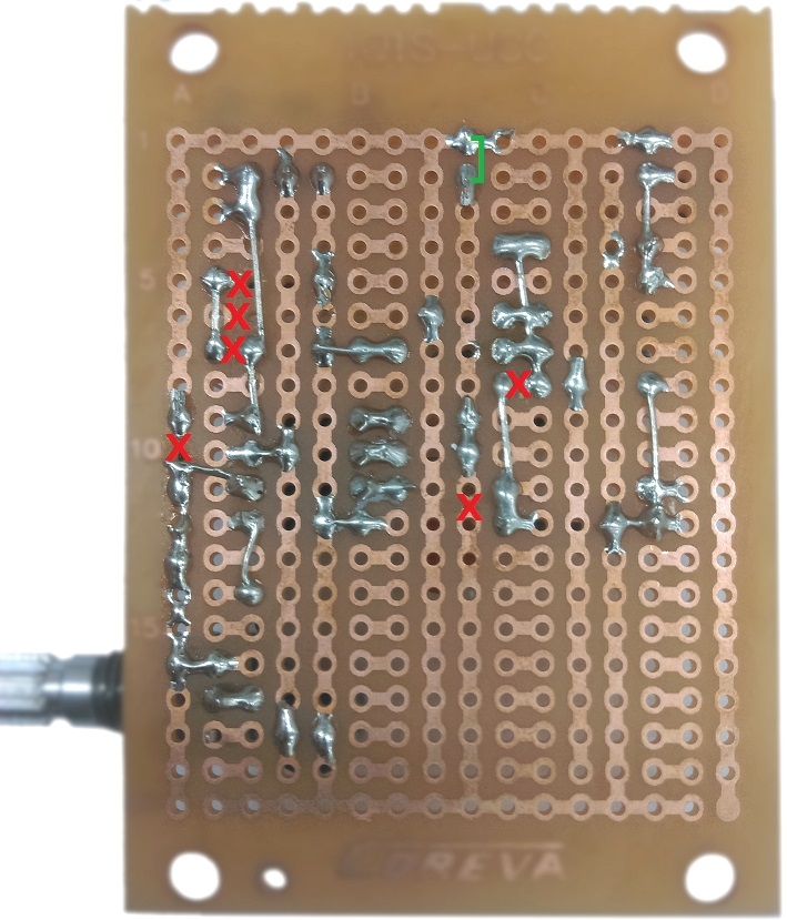
Below is a picture of the underside of the PCB to show the solder connections; We had to make a few cuts in the board to make sure all the connections work, which you can use a hobby or stanley knife (such as HG9955 or TH1916)to make.

One of the main things to realise is the microphone has a polarity and must be connected the correct way.In the images folder for the project we do have a larger image if you want a close up on what to solder.

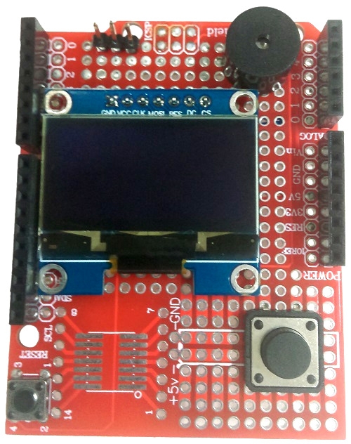
The shield will contain the buzzer, button, and OLED screen

We've placed the button near the bottom so it's a little easier to act as a one-handed device, which you would be able to press the button with your thumb.

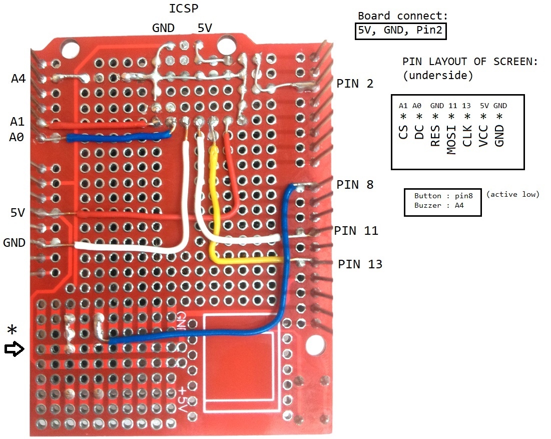
The underside of the prototyping shield is as below, along with the pinouts:

We removed the ICSP header pins and used the 5V and GND connections, as labelled. One easily forgotten connection is that one of the button pins must be connected to ground, then we will set pin 8 as INPUT_PULLUP.

Make sure that the buzzer is orientated the correct way as well, with the positive connecting to A4.

The main .ino is pretty simple to read, as most of the functions are taken out into their own independent source code files.

We did chance to come across a morse code decoder project on the arduino project hub here which has been modified to work with this project.

The original code included a great AdaptiveLogicLevel class which would be great for analogue sensors (such as an LDR), however we won't need that for this project, as we are using a digital logic level.

The general premise is:

  • A Timer fires off every millisecond which puts information into MorseCodeElementProcessor

  • Once the MorseCodeElementProcessor determines there's enough to decode, it signals to the MorseCodeProcessor to output the actual character

  • Each MorseCodeElement is one dit (.) or dah (-)

At the moment, we only have Serial mode working, which is a talkback and communication channel between the Serial Monitor and the microphone/buzzer. Try it out!

Definitely check out the Issues tab on github for how else we can expand this project, as well as clean it up and make it tidier to read. We will be bringing out a github guide soon so if you're not too keen in the github process you can check out some youtube videos, such as this one.

Hold down the button while resetting the unit, you'll get a serial menu opened to select mode. Serial Mode is '1' which works correctly, we can update this readme once the other sections are filled in.

Hold a speaker up to the microphone and play morse code; You will have to turn the pot to try to tune the tone decoder into the correct tone you're looking for. You will know it's the right tone when you can see the Green LED light up.

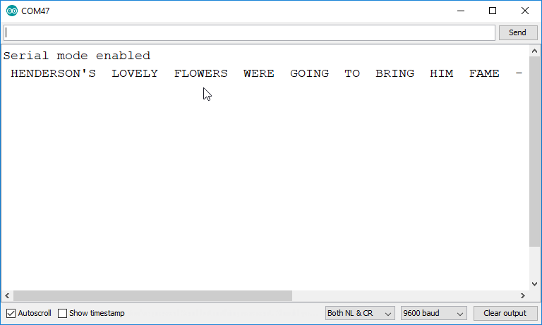
Open the serial monitor, any morse code you find should be decoded and printed out in the Serial channel. You can also send a string to the morse and it will play the tone out of the buzzer.

Any short-wave radio receiver with Single Side-band (SSB) function can receive Morse code to use with this project. Our AR1780 Short-wave Radio with SSB would be perfect!

Every amateur radio band has a section allocated exclusively for Morse code at the lower edge of the band. For example, on the 40m band, you can hear very clear Morse transmissions between 7000 - 7030kHz just after sunset.

On top of this, there are radio beacons in every country that transmit a continuous tone with station identification in Morse code every 30 or 60 seconds.

And of course, youtube.

Similar projects you may be interested in