Micro ROS Controller

Summary
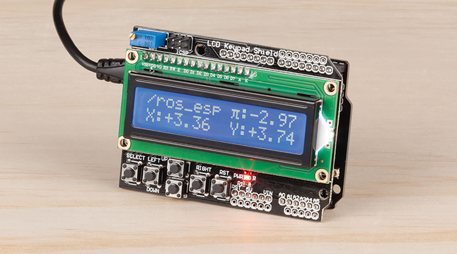
Ever build robots and looking for a neat way to control them? Or have you heard of the Robotic Operating System (ROS) but didn't know where to begin? Then have a look at our new project utilising our popular XC4411 Uno with WIFI board and LCD controller (XC4454).
This tutorial gives you everything you need to set up a ROS environment on your PC and builds a small controller which you can use to control a simulator around on the page. Once you've built it, you can easily transport the controller to control any other ROS robot with a flick of a command. The possibilities are endless.

Materials Required
| 1 | Duinotech UNO r3 Main Board with Wi-Fi | XC4411 |
| 1 | Duinotech Arduino Compatible 2 X 16 LCD Screen Display with Controller | XC4454 |
| 1 | Arduino Compatible 10K Ohm Slider Potentiometer Module | XC3734 |
| 1 | Rotary Encoder Switch with Pushbutton | SR1230 |
| 1 | Arduino Compatible Tri-Axis Digital Tilt Sensor | XC3732 |
| 1 | Duinotech Arduino Compatible 2.5 Inch Colour LCD Touch Screen Display | XC4630 |
Table of Contents
Code | What it is | What to use it for |
|---|---|---|
| XC3734 | Slider Potentiometer | things like throttles, or analogue movement between an upper and lower bound |
| SR1230 | Rotary encoder | Used for infinite turning motion |
| XC3732 | 3 axis tilt sensor | controler orientation detection |
| XC4630 | Touch screen | create your own easy GUI interface, in a portable way. |
What we're building is actually a little bit of a hack. Let's start with the overview.

The ROS2 ecosystem uses a special messaging format called DDS - We won't get too far into the technicals here, but we basically work on ensuring that different components communicate properly by specifying the structure of the message that they send.
This means, for our micro ROS controller device, we'll have to program the message format as well as the DDS infrastructure that goes around it; Some work has been done in this regard, called microros ( check out https://micro-ros.github.io/ ) but unfortunately it doesn't quite fit for our purposes.
Our method is simplier and hackier - We're going to develop a ROS2 node that will both communicate internally to ROS as well as listen to UDP/TCP on the local network, which our ROS controller connects to to send packets back and forth. This method is insecure but it does fulfil the requirements of communication between the two devices, and security can be implemented on top of it at a later time; We'd only recommend this for secure WiFi networks, if not a direct hotspot type of connection so that the ROS PC / robot can block out any connections that aren't the controller.
The first thing we should do to build this set up is actually get ROS running on a robot. What robot? we hear you ask; we'll, if you don't have a robot we can just install ROS on a computer and use the turtlesim simulator program that ros has; That's what you see in the little animation above.
ROS2 should be installable on any modern computer; If you know how to set up virtual machines, (or looking for a reason to give it a try) We'd highly recommend installing Ubuntu linux (or a lightweight version: Xubuntu) into a virtual machine; You can download Virtualbox (HERE) and use that to install xubuntu (HERE).
We'd recommend using LTS releases; at the time of writing it's 20.04 for ubuntu and ubuntu derivatives; we've had problems with the later release of 20.10.
We have given you a setup script ( script.sh) that you can use on your new ubuntu machine:
sudo sh ./mrc/ros2-software/setup.shthis will give you a prompt and try to do things automagically. If you get stuck you should really try following the documentation, as we've tried to just put it together in the script and make it easier, but nothing beats doing it yourself and learning.
Official documentation is here: (We are using version Foxy):
Windows users if you want to install ROS2 on your windows machine, check out: https://index.ros.org/doc/ros2/Installation/Foxy/Windows-Install-Binary/
Note: ROS is a large collection of smaller individual packages, so keep that in mind when you are installing on you system that you also use for work or otherwise. Most of the cases it could be fine, but in other cases it could mean that the examples and code won't work properly if the system isn't set up right.
If you follow the turtle simulator tutorial (HERE) (Which we highly recommend you do, it will only be a 15min diversion), you'll start to understand how ROS2 works.
One thing you must remember when doing anything with ros2 is to actiavte the ros2 environment. If you installed ROS on a ubuntu machine like above, you should find the activation script is in /opt/ros/foxy/setup.bash which you can just run with:
source /opt/ros/foxy/setup.bashor place into your bash.rc file so that it will automatically do it when you open a new shell:
echo "source /opt/ros/foxy/setup.bash" >> ~/.bashrcOnce the activation has happened, you now have access to new ROS commands in the terminal. If you didn't use our setup script, make sure that the turtlesim is installed with sudo apt get ros-foxy-turtlesim and then run the turtlesim program:
ros2 run turtlesim turtlesim_nodeYou should get a screen show up on your computer that will show a turtle in the middle of a blue square. If you want a quick test to see what we're doing here, try running the following command and then use the WASD keys to move:
ros2 run turtlesim turtle_teleop_keyUse Ctrl-C to exit out of it.
The ROS tutorial we linked above will go into detail on how ros works.
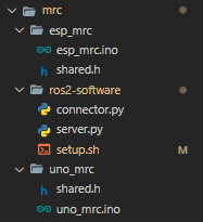
From this, there's three main parts that we've got to program, and they're all located in the mrc/ folder

Putting it simply:
ros2-software is a python program that runs in the ROS space; we'll need to set the computer up for this soon, and is responsible for talking to the robot.
uno_mrc is the uno code that interprets the button presses and shows things on the LCD screen.
esp_mrc this is the underlying ESP portion of the code: this connects from what's happening with the uno_mrc and sendds it to the ros2-software
We'll try and break it down a bit more so you can understand.
This is the first bit of code we'll look at, and figure out how it works; The code looks something like this (simplified):
void loop(){
        char button = getButtonValue();
        if (button != 'x'){
                Serial.write(button);
        }
        while (Serial.available()){
                String data = Serial.readString();
                if (data.startsWith('|')){
                        //print data retreived with data;
                        printPoseInformation();
                }
        }
}
There's really not much to it; Use the serial data to send information to and from the ESP; we pass through the button presses when we detect them, and we receive our robot's pose estimation to display.
When programming the UNO code, make sure you change the DIP switches on the XC4411 to be 3|4 ON and all other switches off, so that you can target the uno properly.
The ESP code is suprisingly shorter and more concise in its function. This code is responsible for communicating with the UNO side of things.
void setup(){
        //remember to change this, in shared.h
        WiFi.begin(WIFI_SSID, WIFI_PASS);
}
void loop(){
        if (Serial.available()){
                processData(); // send UDP data
        }
        if (millis() > timer){
                syncData(); // send TCP data
        }
}
The two functions work differently for different reasons:
We use UDP for movement data; this is usually because of how the buttons work. When we hold down a button the system (uno) will register it a couple of times. You can see this if you run the uno code above while connected via the serial monitor, the "up" button will produce a series of u for serial data, and the same with the other buttons.
Each byte that the ESP receives via serial, if it's one of the 5 button byte values: {'u','d','l','r','s'} it will send this byte via UDP to the ROS host machine ( or the ros2 software we're running).
UDP is an unreliable system, but it makes up for that in speed. So with our system, we might send 100 'u' bytes to the system, but it only takes one to trigger the robot to move. We usually want the robot to move WHEN we press the button, so this system works well and the extra lost data is really not a worry.
For Pose information, we need this to be accurate on the controller so that we know where the robot is. Here, the speed is less important than the accuracy: imagine if the controller was trying to send the number 14,000 m but UDP packet loss dropped the '4', then your position data would be out by 13kms!
This is a trivial example of course, but we're using it to demonstrate the point. We need this data to be accurate so we use TCP which has error checking built into the protocol; we then just make a mock HTTP server (because it was the easiest) so that our ESP can call http.GET(); and get the most recent data, almost like a webpage.
We then just send this pose information over the Serial wire to the UNO for it to display it on the screen.
When programming the ESP, make sure to change the dip switches on the XC4411 to be 5|6|7 ON and all others off; turn 7 off if you want to test via the serial monitor.
This is the meat of the program so we tried to put some comments in these files to help you.
The connector.py program defines a ROS Node that is used to communicate on the ROS platform. ROS uses "subscribers" and "publishers" on "topics" similar to MQTT for the message data; here we've set the system that will publish and subscribe to for our turtlebot simulator
Quick Note: If the Python program doesn't work; make sure that the ros environment is activated ( as mentioned in Activating the ros environment) - if the envionment is activated, then make sure the python dependencies are installed: sudo pip3 install argcomplete flask eventlet flask_socketio
The server.py file is what spins up the Node pin the ROS environment and gets it communicating with the device, it will spin up a small server for pose information on http://your.computer.ip.address:5000 and will listen for UDP packets on port 1337. When it gets data on either of these things, it will translate that over to the ROS architecture as expected.
In order for your micro ros controller to move about turtlesim, you need to have the turtlesim open, the ros2 software running, and then point your communicator to your computer's IP address.
The use of this is completely up to you, but you can see in the video above I just made a simple switch between the 4 buttons and moving the turtle around. In this example, the buttons are sent via UDP and the position / pose of the robot is sent via TCP; this is for both button/reaction speed and for quality of information coming back to the controller.
Try it out and let us know what you build with it; we'd really love to see more ROS2 robots out there, and thanks to RViz and other simulators, it's easy to build robots in simulators, and try to connect it up with real hardware, somewhat similar to what we've done here.
The absolute best way to learn is to just try to write your own software and use this as a bit of a guide; you can then tailor the system to what you have available for you, and perhaps you might have better ideas on how to communicate between the ROS and microcontroller ecosystems.
We're welcoming contributions on this code base, as it's fairly unmaintable at the moment: if you find that something is not clear, or you want more pictures, or you want to change the code, feel free to submit PR and Issues.
Similar projects you may be interested in


.jpg?branch=prod&format=webp&width=428)