Christmas Light Controller
Summary
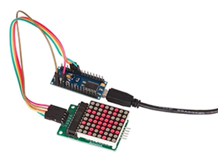
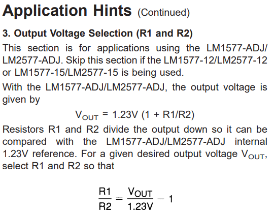
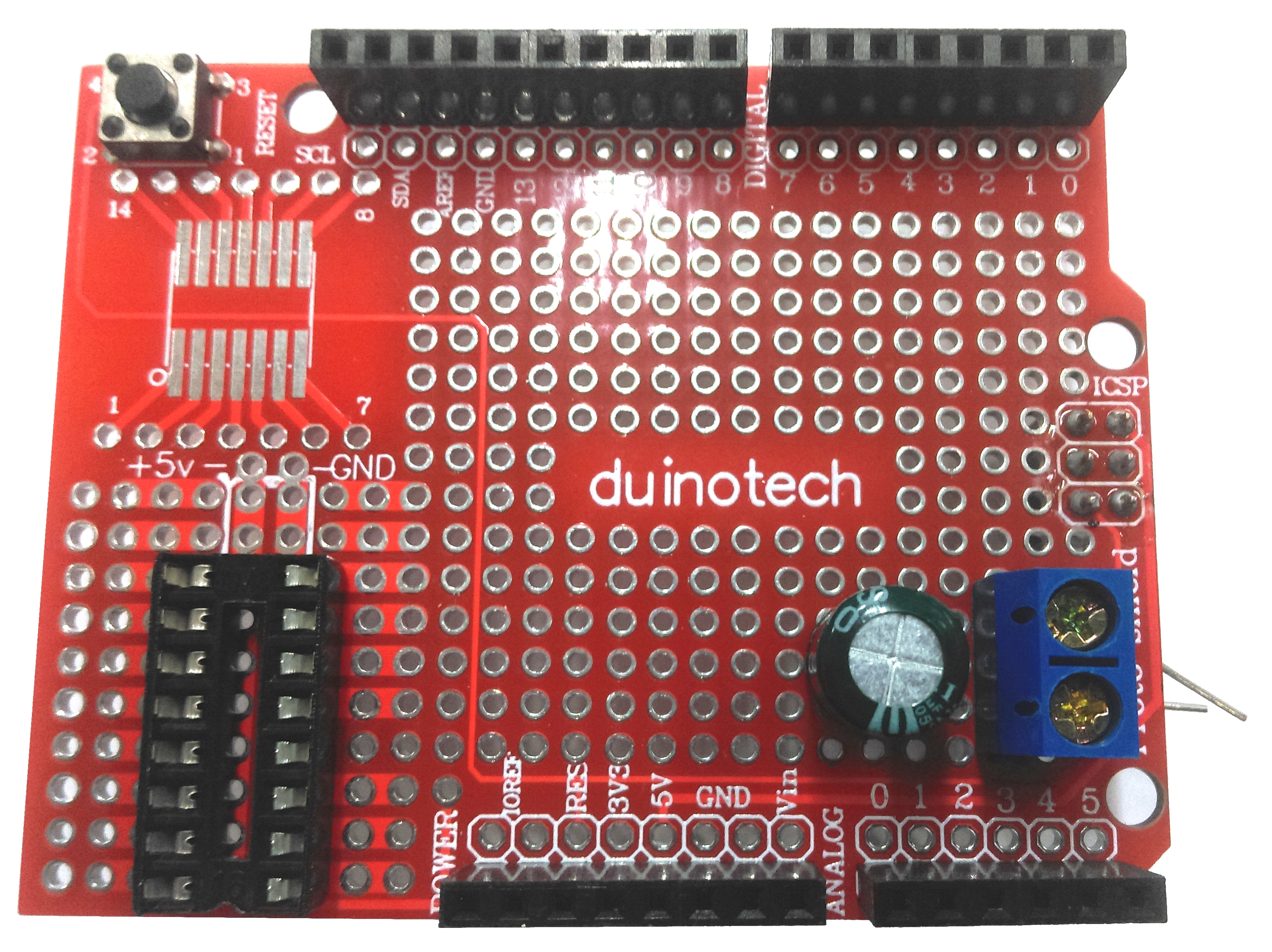
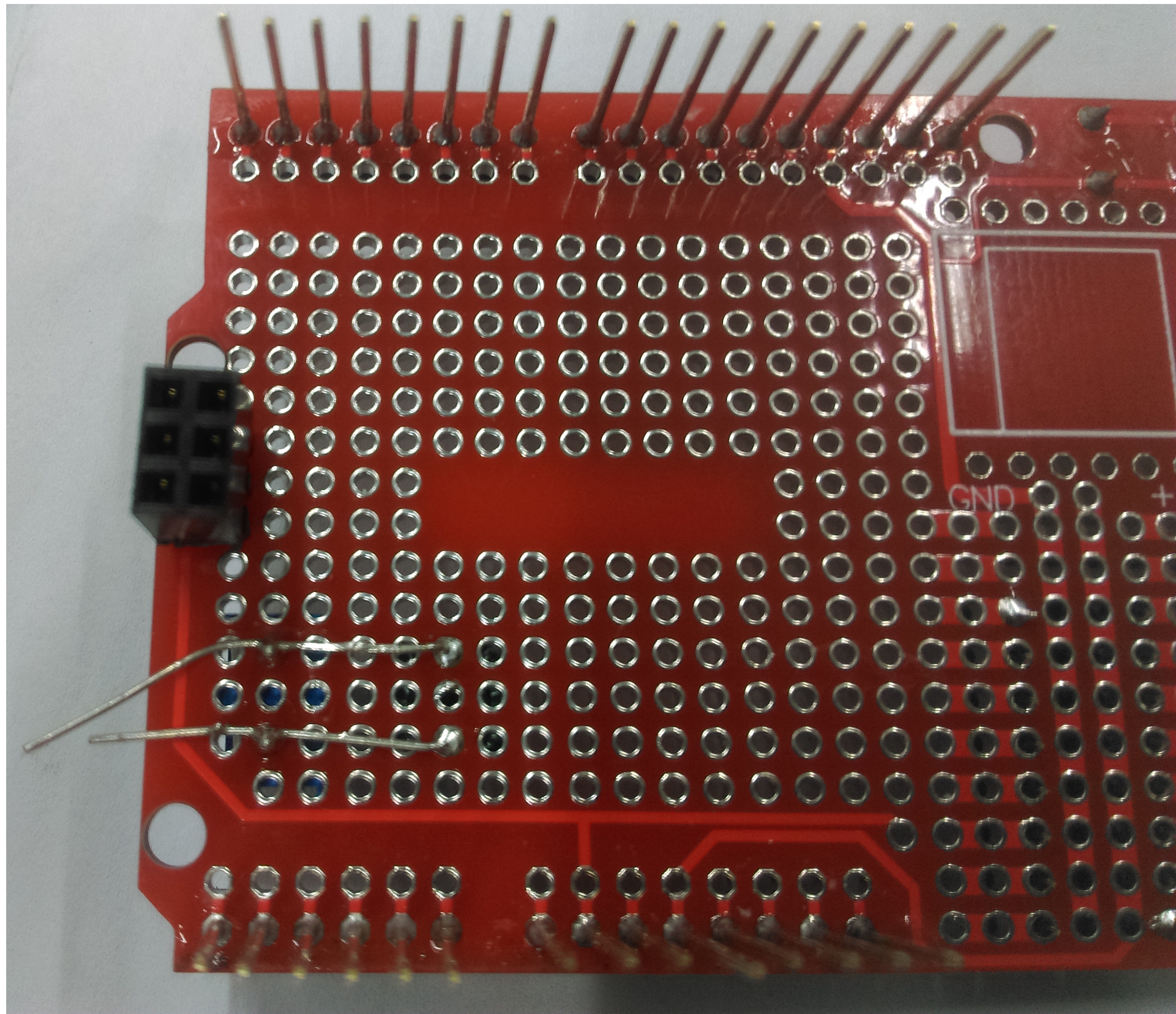
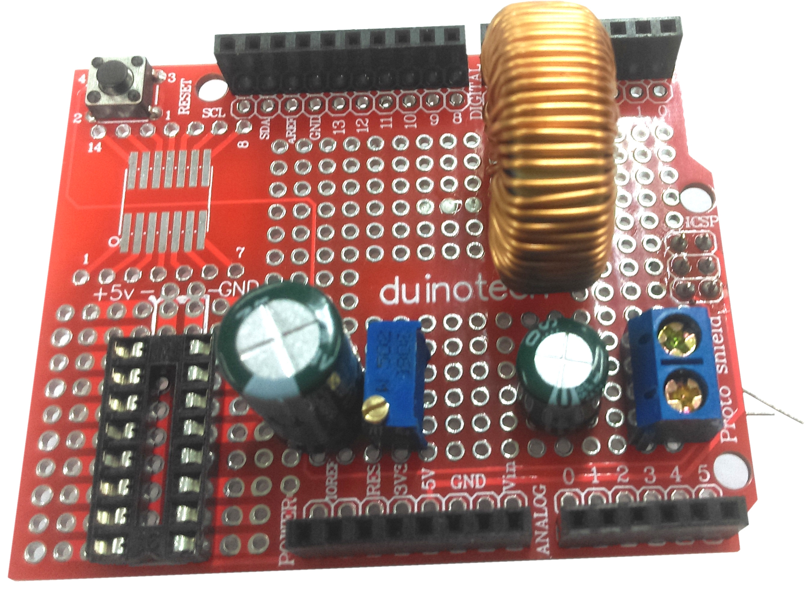
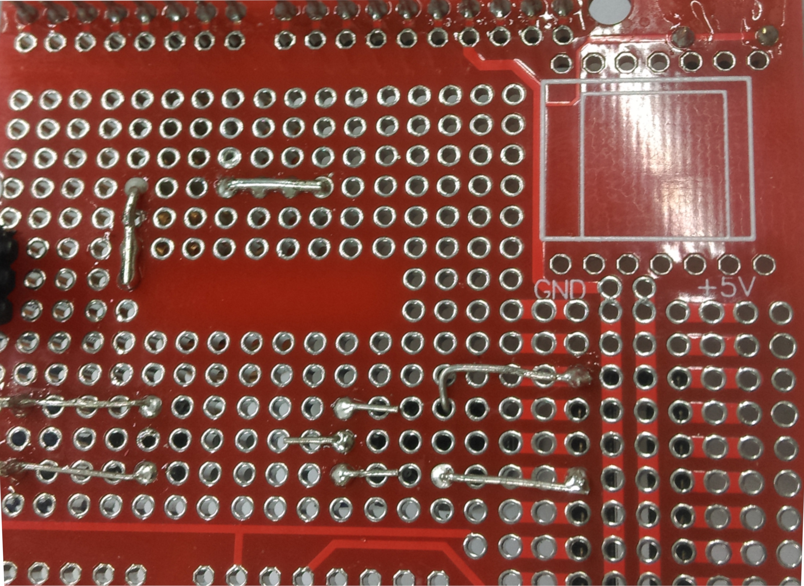
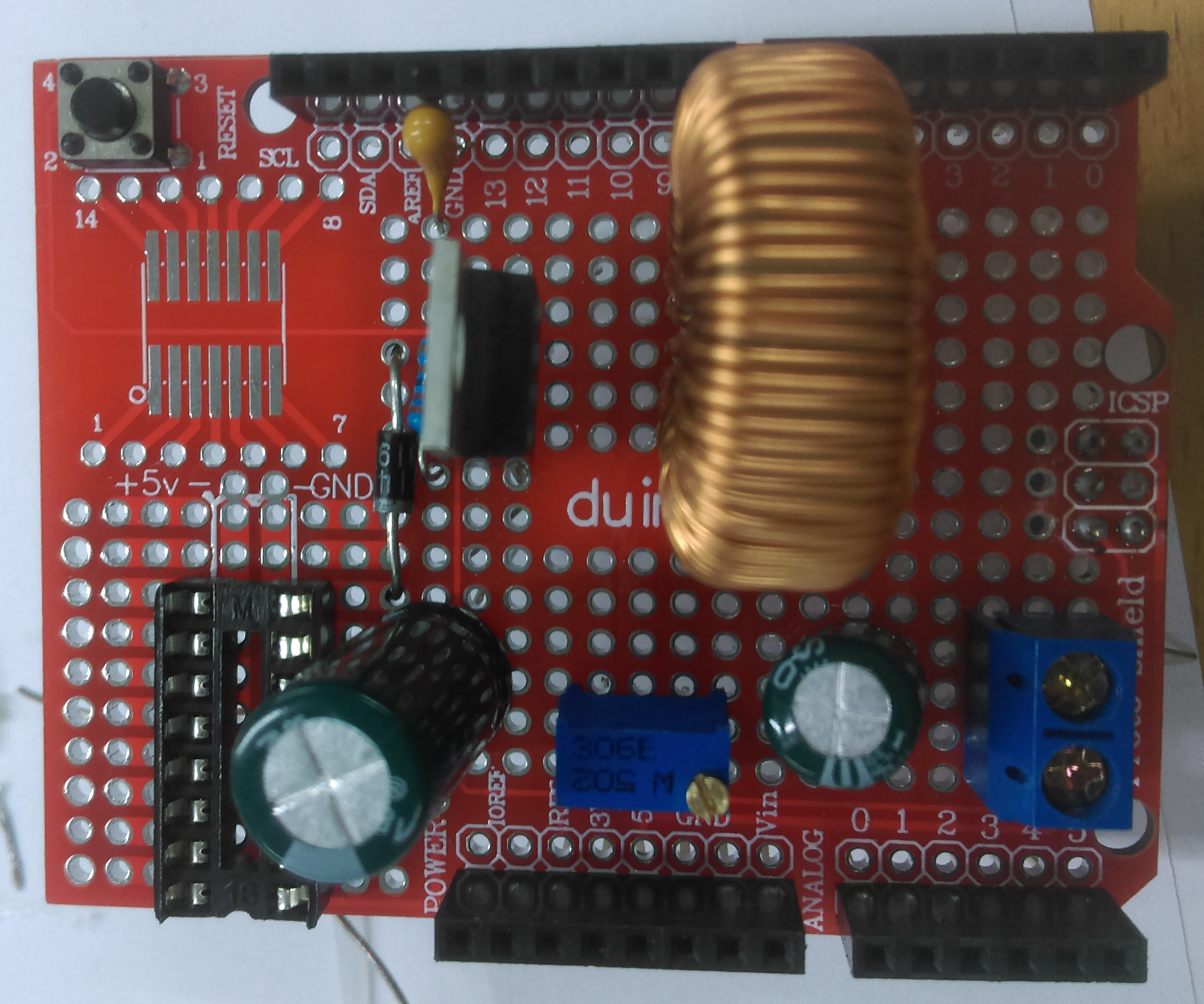
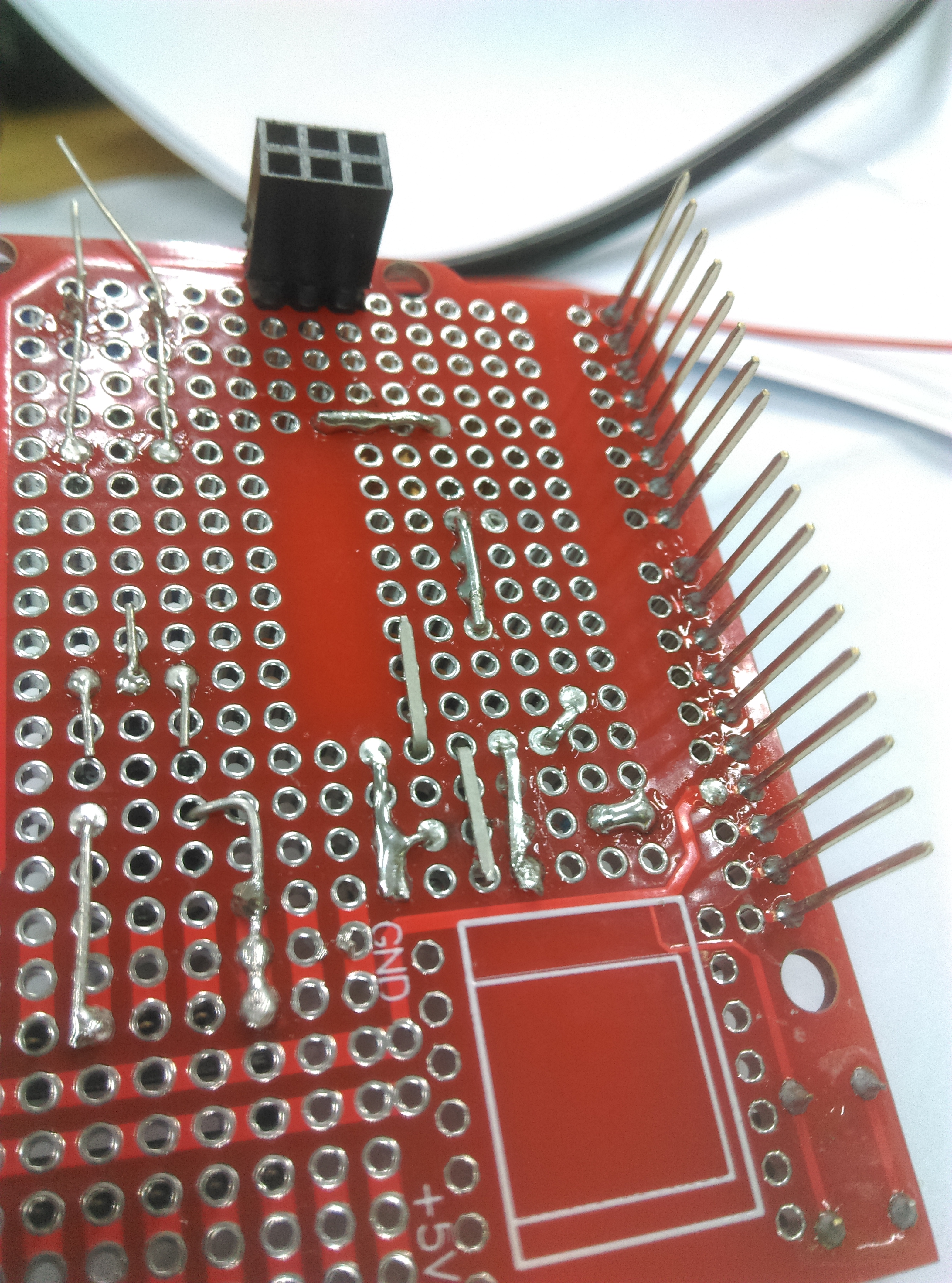
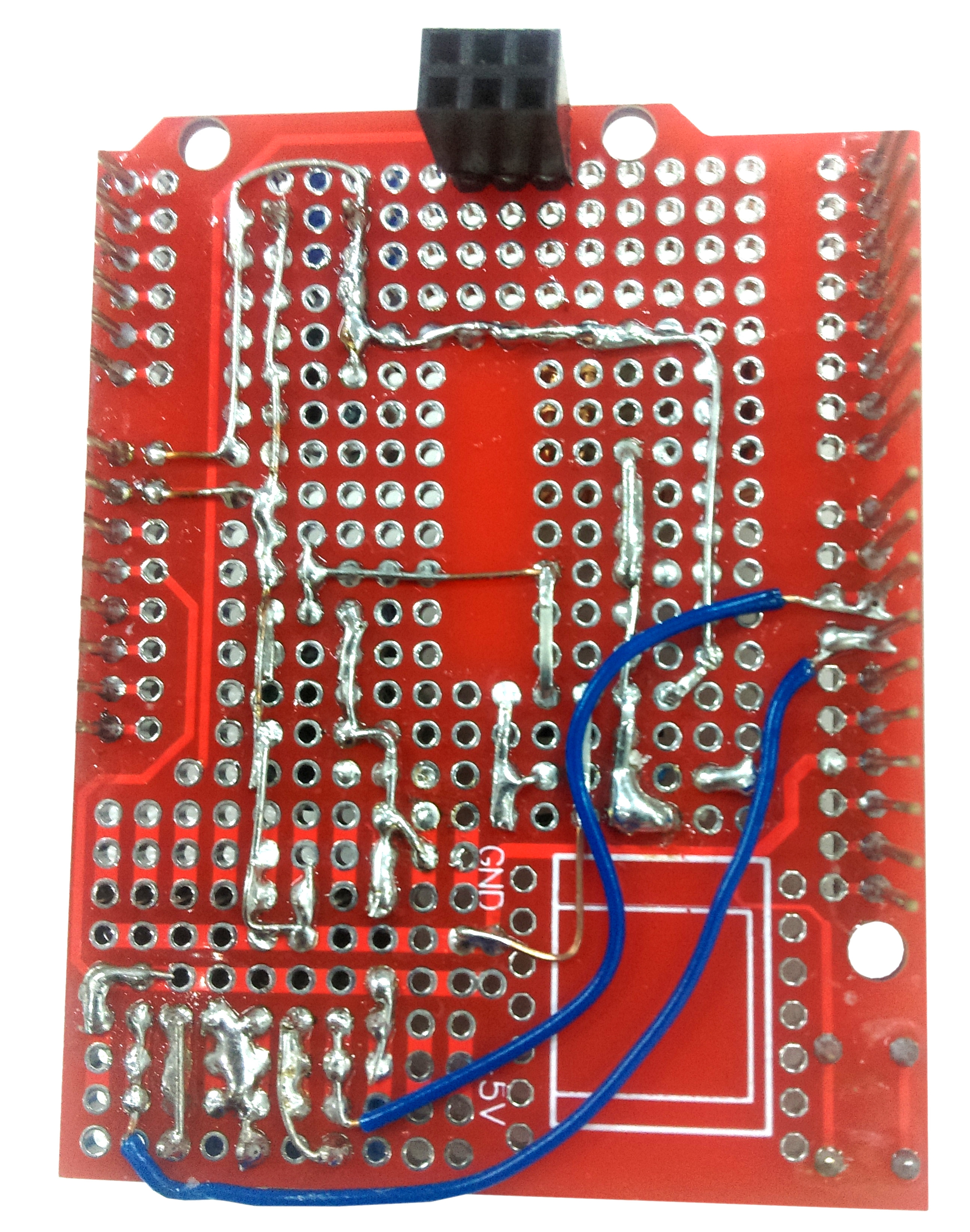
This project uses a few handy components on a traditional UNO prototyping board; Build the module as below then place on top of the UNO.
With the open-source nature of this project you would be able to attach sensors to it if you required. This project uses a few handy components on a traditional UNO prototyping board to make setting up a breeze. Simply build the module then place on top of the UNO, you can even set up your own sensors or use the XC4411 Uno with WiFi to make it IoT controlled.
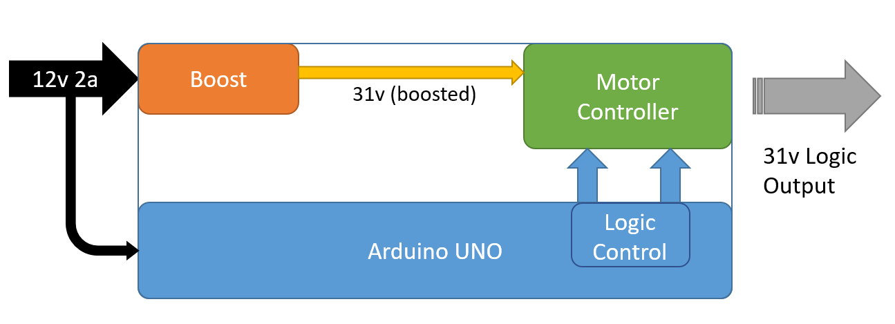
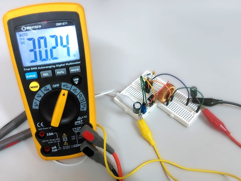
Provides adjustable voltage, between 12 and 40 volts, with two programmable outputs, suitable for most lights. Power by any DC power you have spare, 5-12v.
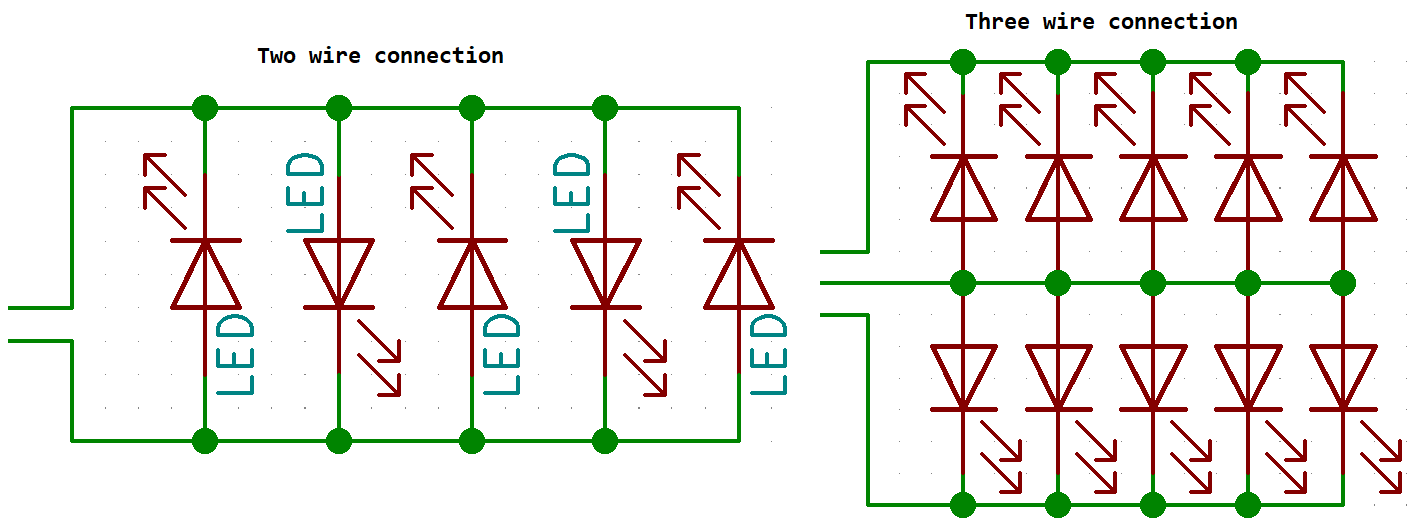
Requires solid-core wires (WH3032) terminal headers (HM3172) if you prefer (not supplied).
Materials Required
| 1 | Duinotech UNO r3 Main Board | XC4410 |
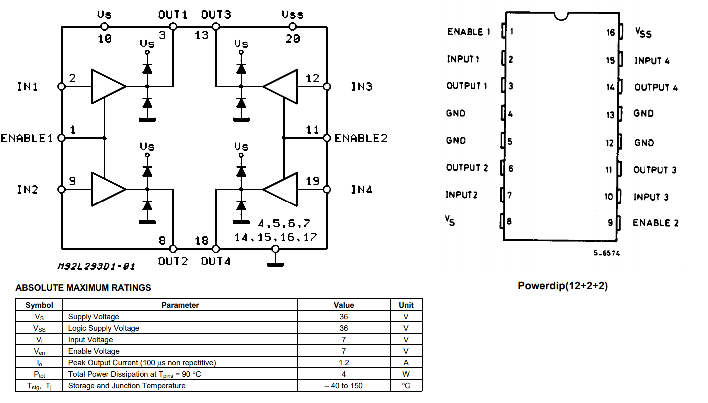
| 1 | L293D Dual Full Bridge Motor Driver IC | ZK8880 |
| 1 | 16 Pin Production (Low Cost) IC Socket | PI6502 |
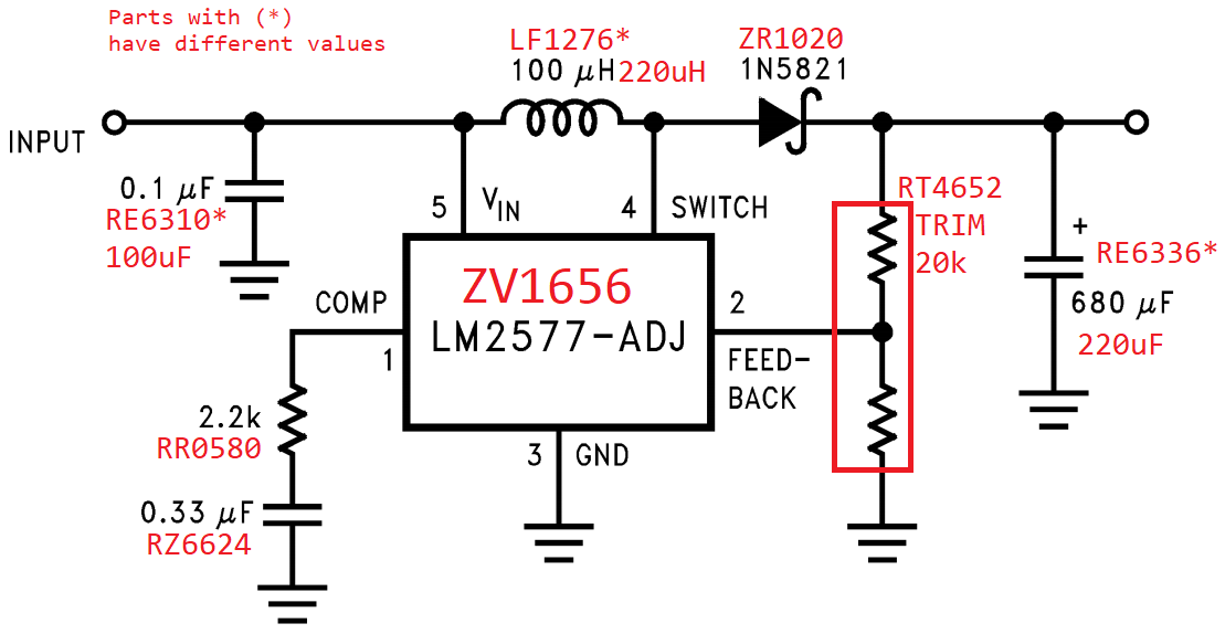
| 1 | LM2577 Boost Regulator IC | ZV1656 |
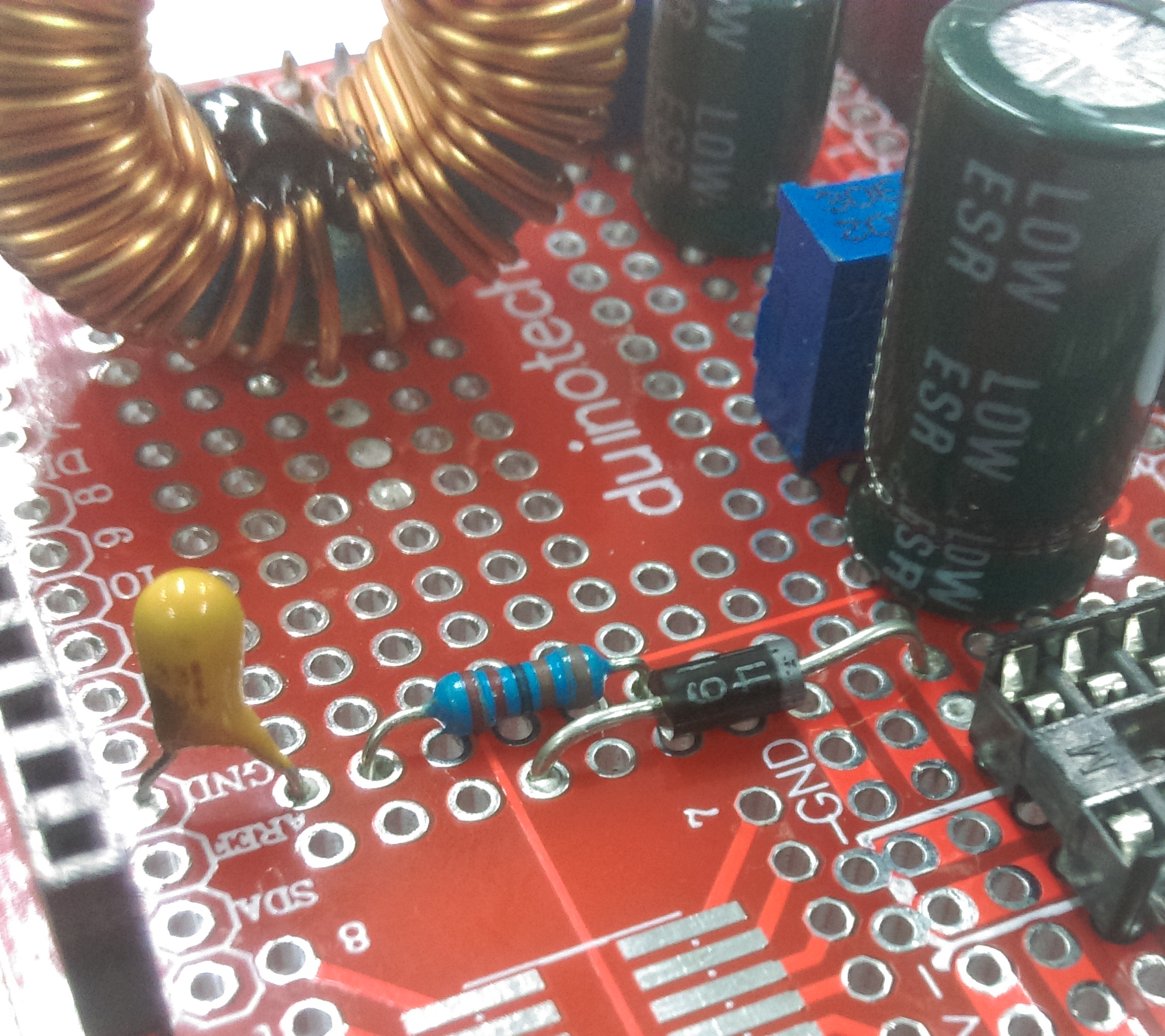
| 1 | 220uH Prewound Ferrite Choke | LF1276 |
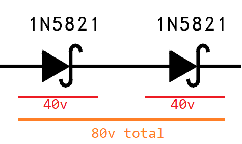
| 1 | 1N5819 Schottky Diode - 40V 1A DO41 | ZR1020 |
| 1 | Duinotech Arduino Compatible Prototyping Shield | XC4482 |
| 1 | 100uF 16VDC Low ESR Electrolytic Capacitor | RE6310 |
| 1 | 220uF 35VDC Low ESR Electrolytic Capacitor | RE6336 |
| 1 | 330nF 35VDC Tantalum Capacitor | RZ6624 |
| 1 | 20Kohm Spectrol 25 Turn Trimpot | RT4652 |
| 1 | 2.2k Ohm 0.5 Watt Metal Film Resistors - Pack of 8 | RR0580 |
Table of Contents


Future Improvements
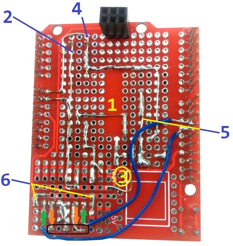
The complexity of this project lies on building the prototyping shield, but once that has finished you can simply connect that on any arduino-shield compatible device, and still use many of the pins available on the arduino;
If you want to use SPI on the arduino it would be a good idea to change pin11 to be pin9 or similar, as pin 11 is the MOSI connection for SPI devices.
Some suggestions:
A light sensor (XC4446 or similar) to turn both pins LOW during daylight hours.
An audio sensor (XC4438) along with an FHT library to provide beat detection and dance the lights to the music (check our music beat bar project for inspiration!).
You could also use our new Uno with WiFi which includes an ESP866 to host a web-app, which can then communicate with the arduino using Serial.read and Serial.write commands.
Further reading
Not much here for this project, happy hacking and Merry Christmas 😄
Similar projects you may be interested in
.jpg?branch=prod&format=webp&width=428)