Progress Bar

Skip to main content

Jaycar
...

Power Usage Monitor

Power Usage Monitor

Difficulty
Power

Summary

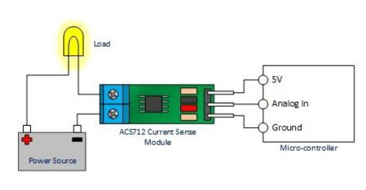
In this project we built a current meter using the AC712 current sensor, instead of just displaying or reporting current measurements we made the project a little more interesting by calculating power consumption (which is just POWER = CURRENT x VOLTAGE), and reporting the power consumption via email. To make this project even more interesting we allow the user to set a daily power consumption limit, if the power consumption of the device you are monitoring reaches 25% of the set limit, you will receive a notification, you will receive another notification at 50% and when the device has reached the set power usage threshold. If all is well and no limits are exceeded, you will still receive an email notification at the end of each day with the daily usage for that day.

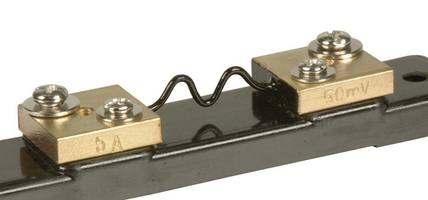
The AC712 sensors is capable of measuring both AC and DC current, and come in three models a 5A, 20A and 30A models. We are using the 30A model (XC4610), which means you can use this model to measure most current sources around t5he home including mains (240V AC). We do not recommend that you connect the unit to a mains outlet unless this work is carried out by a licenced electrician in accordance with the relevant Australian Electrical safety standards. You can safely connect the AC712 to low voltage sources and appliances such as 12V or 24V batteries, or low voltage AC devices.

Materials Required

1Wi-Fi Mini ESP8266 Main BoardXC3802
1Arduino Compatible Wi-Fi Mini Prototyping ShieldXC3850
1Arduino Compatible 30A Current Sensor ModuleXC4610
1Hook-Up Wire Pack - 2 metresWH3025
140 Pin Female Header StripHM3230

There are plenty of example code for the AC712 on the Internet, we have chosen the AC712 library developed by Murat Demirtas, you can download this library at:

https://github.com/muratdemirtas/ACS712-arduino-1

Because we are very lazy, we reused, verbatim, the Gmail email sender code published earlier in the Intruder Alert project (https://www.jaycar.com.au/intruder-alert). The set-up of the Gmail account is described in detail under that project, so we will not repeat it here.

This project is very easy to build, only three wires from the AC712 to the ESP8266 D1 board, as shown in Figure 1 below. The Output pin from the AC712 is connected to the Analog In pin on the ESP8266 (A0).

Because the AC712 and ESP8266 D1 Mini are so small you can fit this project in almost any small enclosure, but be sure to observe Electrical safety if using high voltage sources. Only two wires from the AC712 to be connected in series with the load current you are measuring as depicted in Figure 2 below.

First unzip the code file, you see three files, these files are to be located under the same directory in order for the code to compile.

Power_usage_Monitor.ino

This is the Arduino IDE source code file

Gsender.h

This is the header file needed to run the code. You will only ever need to update this file once, with your Gmail details.

Gsender.cpp

This is the library code file. You will not need to modify this file.


From the Arduino IDE open the WiFi_Intruder_Alert.ino file. You will notice three tabs on the tiop of the main editor scree, click on the Gsender.h to view this file. There are only three lines which need to be updated in this file, to tell the application your email address, and login details, as shown below:

const char* EMAILBASE64_LOGIN = "asdfkjlakjsd;lkj";
const char* EMAILBASE64_PASSWORD = "asdfadfaskljdfakl";
const char* FROM = "your gmail address@gmail.com";

You will notice that the EMAILBASE64_LOGIN and EMAILBASE64_PASSWORD are encoded, that is because you may not want to insert your private login details as plain text, so we use base64encode.org to generate the encoded version of our plain text email login credentials.
Note, this is not secure; it's only obscure.

Open the main source code file Power_Usage_Monitor.ino, you will need to review and possibly edit the following parameters:

â–º Set the daily usage power limit, this is the threshold usage that will be used to send notification if exceeded. You can locate this parameter in the source code file line shown below;

#define daily_usage_limit 1000 // This is the daily usage limit

â–º Now you need to specify the type of current measurement, whether you are measuring DC or AC current. Set the measurement_type variable to DC_curnt or AC_current, as illustrated below;

int measurment_type = DC_current; // change this to the type of current DC or AC

â–º Now you need to specify the voltage level, in order to correctly calculate the power consumption. Depending on the type of current you are measuring set the Vdc or Vac parameter to the voltage source you are measuring, as shown below;

float Vac = 12; // Edit this value to match the voltage level in your application.
float Vdc = 12; // Edit this value to match the voltage level in your application.

When powering on the Power Usage Monitor make sure that no devices are attached upon start-up, because the unit calibrates itself on start-up. This is done in the setup routine by the following line of code:

sensor.calibrate();

Similar projects you may be interested in

Power
Bluetooth Power Point
Difficulty

Benchtop Power Supply
Power
Benchtop Power Supply
Difficulty

Power
Hand Gesture Power Socket
Difficulty

Power
DIY power leads with Anderson High Current Connectors
Difficulty